 |
| FEATURES |
● Max switching capacity up to 30/40A.
● PCB mounting or quick connect terminals.
● Optional mounting bracket.
● 1 Form A, 1 Form B, 1 Form C and 2 Form A arrangements |
|
|
 |
|
 |
UL FILE NO:
TUV FILE NO:
CE DECLARATION OF CONFORMITY
CQC FILE NO:
|
|
 |
| ORDERING INFORMATION |
| 961 |
A |
- |
1C |
- |
12 |
D |
M |
P |
|
|
|
|
|
|
| 1 |
2 |
|
3 |
|
4 |
5 |
6 |
7 |
|
|
|
|
|
|
|
1 |
Model Number
961 |
2 |
Contact Load
Nil = 30A
A = 40A
|
3 |
Contact Arrangement
1A = 1 Form A (SPST-NO)
1B = 1 Form B (SPST-NC)
1C = 1 Form C (SPDT)
2A = 2 Form A (DPST-NO)
|
4 |
Coil Voltage
6-24V |
5 |
Coil Type
D:DC |
6 |
Dust Cover Type
Nil = Standard Dust Cover
M = Mounting Bracket Dust Cover
W = Weather Proof Type
|
7 |
Terminal Form
Nil = Standard Type
P = P.C.B. Type
|
|
| |
| COIL RATINGS (at 20℃) |
COIL
TYPE |
Coil Nominal
Voltage (V) |
Coil
Resistance
(Ω+-10%) |
Pick-Up
Voltage (V)
<= |
Drop-Out
Voltage (V)
>= |
Nominal
Current
(mA) |
DC Standard Coils |
6 |
22.5 |
3.6 |
0.6 |
267 |
| 12 |
90 |
7.2 |
1.2 |
133 |
| 24 |
360 |
14.4 |
2.4 |
67 |
|
|
| * Max Continuous Voltage at 20℃:? 130% of Coil Nominal Voltage. |
CONTACT RATINGS |
| ●Contact Arrangement |
|
|
1 Form A (SPST-NO) |
|
1 Form B(SPST-NC) |
|
1 Form C (SPDT) |
|
2 Form A (DPDT) |
●Max. Switching Power |
|
|
|
1 Form A (SPST-NO) |
480W |
|
1 Form B(SPST-NC) |
480W |
|
1 Form C (SPDT) |
480W |
|
2 Form A (DPDT) |
480W |
●Max. Switching Voltage |
|
|
1 Form A (SPST-NO) |
12VDC |
|
1 Form B(SPST-NC) |
12VDC |
|
1 Form C (SPDT) |
12VDC |
|
2 Form A (DPDT) |
12VDC |
● Max. Switching Current |
|
|
|
1 Form A (SPST-NO) |
40 A |
|
1 Form B(SPST-NC) |
40 A |
|
1 Form C (SPDT) |
40 A |
|
2 Form A (DPDT) |
40 A |
●Contact Resistance |
|
|
1 Form A (SPST-NO) |
<= 50 mΩ |
|
1 Form B(SPST-NC) |
<= 50 mΩ |
|
1 Form C (SPDT) |
<= 50 mΩ |
|
2 Form A (DPDT) |
<= 50 mΩ |
●Resistive Load |
|
|
|
1 Form A (SPST-NO) |
|
|
1 Form B(SPST-NC) |
|
|
1 Form C (SPDT) |
|
|
2 Form A (DPDT) |
|
●Contact Material |
|
|
1 Form A (SPST-NO) |
Ag Alloy |
|
1 Form B(SPST-NC) |
Ag Alloy |
|
1 Form C (SPDT) |
|
|
2 Form A (DPDT) |
Ag Alloy |
●Inductive Load |
|
|
1 Form A (SPST-NO) |
|
|
1 Form B(SPST-NC) |
|
|
1 Form C (SPDT) |
|
|
2 Form A (DPDT) |
|
●Pilot Duty Load |
|
|
1 Form A (SPST-NO) |
|
|
1 Form B(SPST-NC) |
|
|
1 Form C (SPDT) |
|
|
2 Form A (DPDT) |
|
●Rating Load |
|
|
1 Form A (SPST-NO) |
961: 30A 12VDC 961A: 40A 12VDC |
|
1 Form B(SPST-NC) |
961: 20A 12VDC 961A:30A 12VDC |
|
1 Form C (SPDT) |
NO: 30A 12VDC NC: 20A 12VDC 961A: NO: 40A 12VDCNC: 30A 12VDCNC: 30A 12VDCNC: 30A 12VDCNC: 30A 1 |
|
2 Form A (DPDT) |
961: 2 x 30A 12VDC 961A:2 x 40A 12VDC |
●Tv Rating |
|
|
1 Form A (SPST-NO) |
|
|
1 Form B(SPST-NC) |
|
|
1 Form C (SPDT) |
|
|
2 Form A (DPDT) |
|
●Remark |
|
|
1 Form A (SPST-NO) |
|
|
1 Form B(SPST-NC) |
|
|
1 Form C (SPDT) |
|
|
2 Form A (DPDT) |
|
|
|
CHARACTERISTICS |
| ●Electrical Life |
100,000 |
●Mechanical Life |
10,000,000 |
●Initial Insulation Resistance |
Min. 100MΩ 500VDC |
●Contact Resistance (Initial) |
≤50mΩ |
●Operate Time |
≤10ms |
●Release Time |
≤10ms |
●Initial Dielectric Strength |
50/60Hz 500VAC 1 min. (between open contact)
50/60Hz 500VAC 1 min. (between contact and coil)
|
● Vibration Resistance |
Malfunction: 10 to 40Hz at Double Amplitude of 1.27mm
Destructive: 10 to 40Hz at Double Amplitude of 1.27mm
|
●Shock Resistance |
Malfunction: 10G (11ms) / Destructive: 100G (6ms) |
●Ambient Temperature |
-40℃~+85℃ |
| ●Relative Humidity |
85% at 40℃ |
| ●Unit Weight |
Approx. 30g |
| ●Remark |
|
|
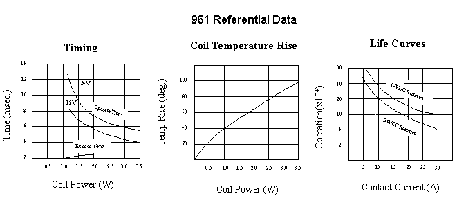
| Referential Data |
 |
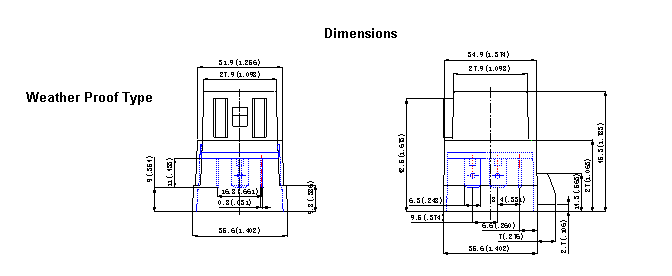
| OUTLINE DIMENSIONS |
 |
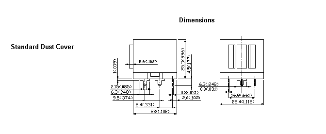
| OUTLINE DIMENSIONS |
 |
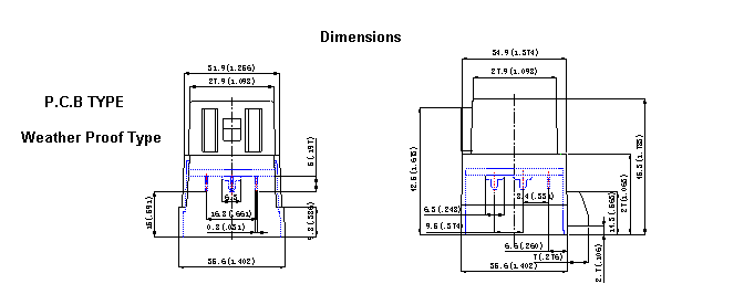
| OUTLINE DIMENSIONS |
 |
| OUTLINE DIMENSIONS |
 |
| OUTLINE DIMENSIONS |
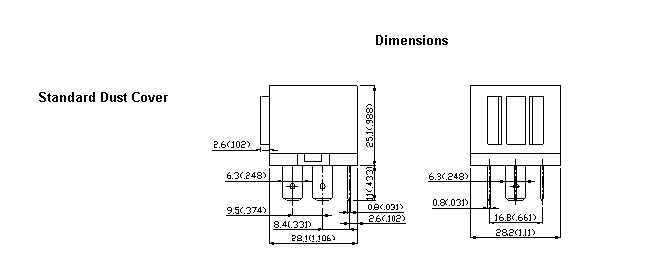 |
| OUTLINE DIMENSIONS |
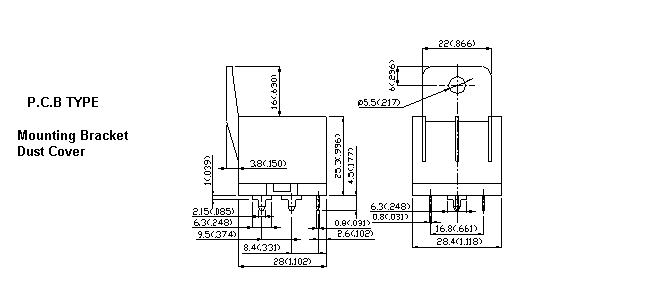 |
| Internal Connections |
 |
| Drilling Plan |
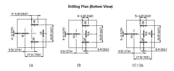 |
|
961 Series Relay.pdf Download  |
|

